Loop-Based Multi-Sensor Calibration Optimiser


Sensors are a crucial part of autonomous vehicles, drone navigation, localisation, mapping, manufacturing and various other robotics applications. In order to extend the field of view and procure appropriate depth information of the environment, multiple sensors are mounted on the machines. Software tools fuse the information from multiple sensors together using sensor calibration parameters. Hence, sufficiently high accuracy of sensor calibration is required for high-quality sensor fusion leading to perfect perception models.
At Deepen.AI, we have developed a Calibration Optimiser to rectify the minute errors in multiple sensor calibrations resulting in highly accurate sensor fusion. Calibration Optimiser works for multiple sensors forming a closed loop. A closed loop is formed between multiple sensors when all the calibration pairs are calculated such that a path from any sensor to itself can be completed. For example, suppose there are three sensors: S1, S2 and S3 mounted on a vehicle with calibration parameters between S1-S2, S2-S3 and S1-S3. A closed loop is formed when you consider three sensors as nodes in a graph network and the calibration between them as edges.
We showcase the efficiency of the optimiser’s algorithm using an experiment conducted in a simulated environment. We construct an environment with three camera sensors pointing towards a checkerboard with an overlapping field of view, forming a closed loop with perfect stereo-camera calibration parameters between each of the camera pairs (as shown below). Although the optimiser can handle any type of sensor, we consider cameras for the sake of explanation.
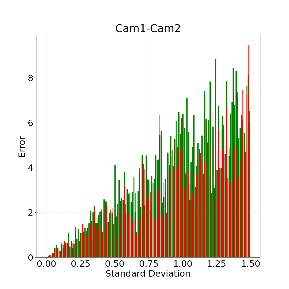
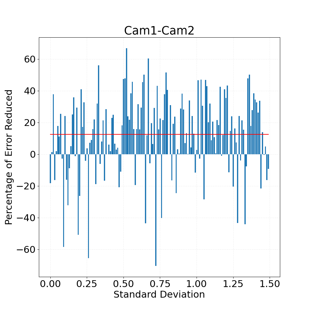
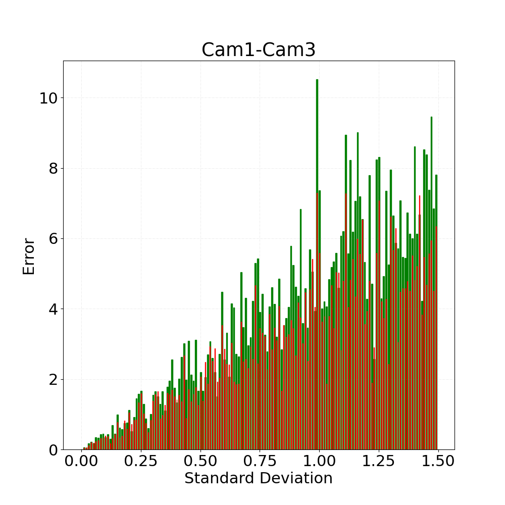
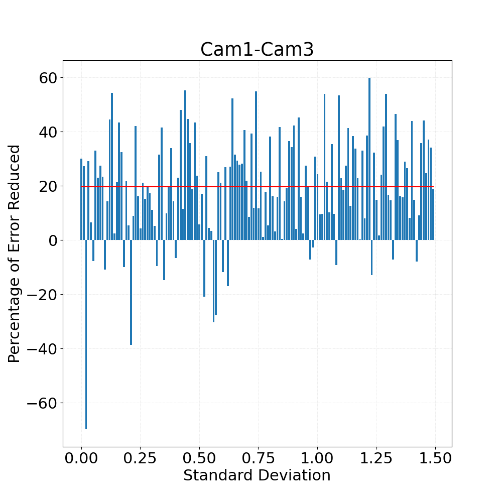
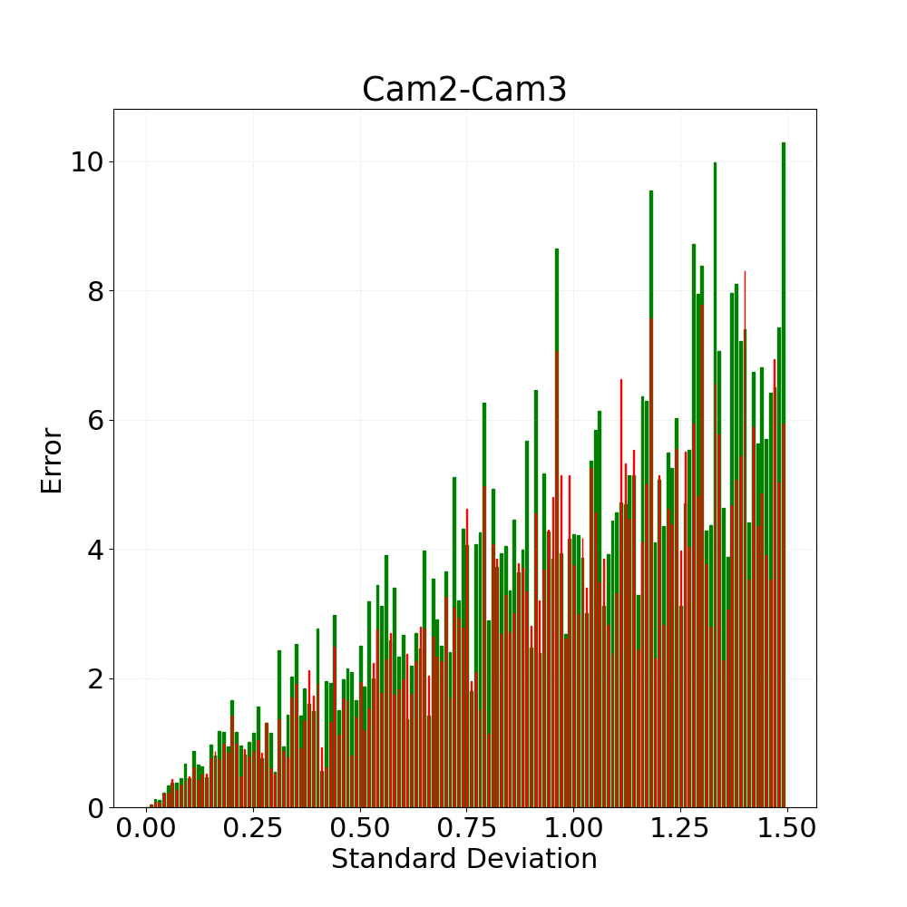
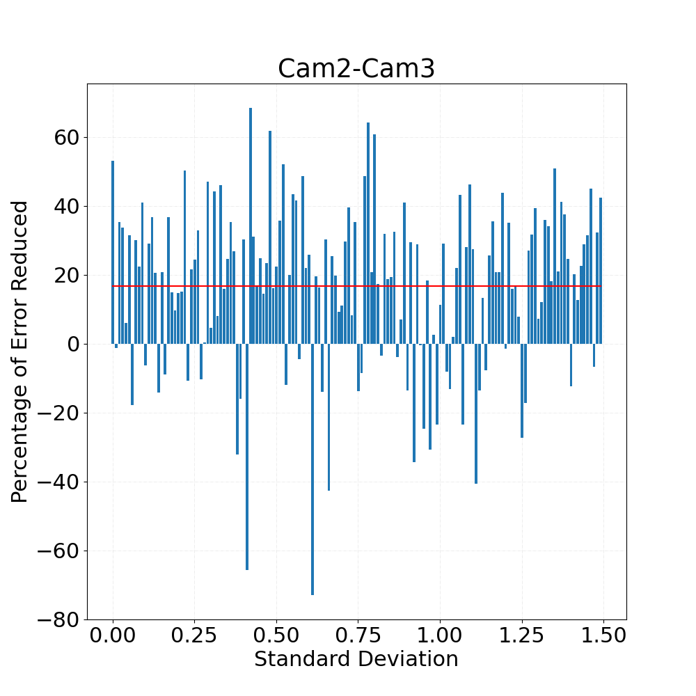
In order to showcase the working of the algorithm, we synthetically add error derived randomly from normal distribution of varying standard deviation and zero mean to each of the perfectly calculated parameters of the three stereo-camera calibration pairs: Cam1-Cam2, Cam2-Cam3 and Cam1-Cam3. After running the optimization using the Calibration Optimiser tool, we evaluate the performance of the algorithm by plotting a curve indicating the amount of error in Y axis and amount of standard deviation added in X axis. Below are the three graphs for the three calibration pairs where the green bars indicate the synthetic error introduced in each calibration and the red bars represent the amount of error after optimization compared to the originally calculated ground truth. In most cases, calibration error is reduced after optimization. There are a few rare cases where optimization increases calibration error because the optimization converges to a solution further away from the ground truth. On average, we observe that an average of 18-20% of the synthetic error was reduced per calibration. After numerous such experiments with varying numbers of sensors, we verified that our algorithm reduces the error by at most 1/N of its original value where N represents the number of sensors in the loop. Note that this result assumes that all calibration errors are independent and evenly distributed among all calibrations.
The use of our Calibration Optimiser on top of the techniques used to calculate the calibration in the first place (stereo calibration in the given example) can reduce the error effectively to reach a better accuracy for sensor fusion. Do check out our documentation for more information on the UI for Calibration Optimiser. Also, visit our website to know more about our Calibration Suite and schedule a demo.